Showing posts with label VERILOG AMS. Show all posts

Wednesday, March 18, 2020

Verilog AMS: DUT and testbench code example: Voltage deadband amplifier using Cadence xrun

Verilog AMS: DUT and testbench code example: Voltage deadband amplifier using Cadence xrun


Here is an example of a simple Verilog AMS DUT ( Design Under Test ) of Voltage deadband amplifier ( from my previous post Verilog AMS: Code examples) with its simple Verilog AMS testbench infrastructure.


Also here  is included all files necessary to run the simulation using Cadence xrun command and an example of a possible file directory structure for developing potentialy  multiple Verilog AMS DUT’s
and their respective tests/testbenches.


The files directory structure consists of the following directories :


  • DUT_VAMS:  where all Verilog AMS DUT’s are kept and in this case there is only one, Voltage deadband amplifier:
    • DUT_VAMS/vdba.vams 


  • TESTBENCH: where all verification infrastructure files are kept including:
    • Cadence files necessary to run xrun command, the files that could be shared with multiple Verilog AMS DUT’s and their respective tests/testbenches,  such as: 


      • TESTBENCH/cds_globals.vams:
        `include "disciplines.vams"

        module cds_globals; 
// Global Signals electrical \gnd! ;
ground \gnd! ; wire \vdd! ;
// Design Variables dynamicparam real VDD = 1.8;

endmodule


      • TESTBENCH/probe.tcl:


# define the database for the waveforms database -open waves -into waves.shm -default # probe all probe -create -database waves -all -depth all # run simulation run 1s


    •  TESTBENCH/amscf.scs:

// **************************************************************** // AMS simulation control file for xrun netlist based flow // **************************************************************** simulator lang=spectre // global signals global 0 vdd! // model deck // ams configuration options amsd{ // set the connect rule power supply ie vsup=1.8 } // run a little bit beyond 1s so that simvision // will be active after 1s of transient simulation tran tran stop=1.1 annotate=status


    • A simple Voltage deadband amplifier test/testbench:
      • TESTBENCH/top_vol_deadb_amp.vams 


  • VERIFICATION: Verilog AMS simulation of the DUT is run from here, with a simulation script like this:
    • VERIFICATION/SCRIPTS/run_simulation_voltage_deadband_amplifier
      • Needless to say, the directory VERIFICATION/SCRIPTS could contain all “run simulation” scripts for all DUT’s and in this case it is a home of a “run simulation” script of Voltage deadband
amplifier simple verification script: run_simulation_voltage_deadband_amplifier.tcl:

#!/bin/bash
# run_simulation_voltage_deadband_amplifier.tcl
export DUT_VAMS=./../DUT_VAMS/ export TESTBENCH=./../TESTBENCH/ xrun \ $DUT_VAMS/vdba.vams \ $TESTBENCH/top_vol_deadb_amp.vams \ $TESTBENCH/cds_globals.vams \ $TESTBENCH/amscf.scs \ -timescale 1ns/1ns \ -iereport \ -access +rwc \ -input $TESTBENCH/probe.tcl \ -gui


Here is a summary of all the files and their respective directories in this example (all the files are included in this post Verilog_AMS_VDBA.zip ):


./TESTBENCH/cds_globals.vams
./TESTBENCH/probe.tcl
./TESTBENCH/amscf.scs
./TESTBENCH/top_vol_deadb_amp.vams
./VERIFICATION/clean
./VERIFICATION/SCRIPTS/run_simulation_voltage_deadband_amplifier
./DUT_VAMS/vdba.vams


Verilog AMS implementation  DUT of Voltage deadband amplifier is very simple: the amplifier will “amplify” input voltage signal with the gain of 1, for any voltage except in a “deadband” between 1 -2 V:


// vdba.vams
`include "disciplines.vams"
`timescale 1ns / 1ns 
module vdba(in, out);
input in ;
output out ;
electrical in, out ;


parameter real vin_low =  1.0 ; 
parameter real vin_high = 2.0 ;
parameter real gain = 1 from (0:inf) ;


analog begin
if (V(in) >= vin_high) begin
        
  V(out) <+ gain* V(in)             ;
end
else if (V(in) <= vin_low) begin
  V(out) <+ gain* V(in)            ;
end
else begin
V(out) <+ 0 ;
end
end


endmodule


Verilog AMS implementation of a simple ( not self-checking ) Voltage deadband amplifier  test/testbench of the DUT do a following:  
  • increments DUTs  input voltage every 1 ns for 0.1V until it reaches 5V:


// top_vol_deadb_amp.vams
`include "disciplines.vams"
`timescale 1ns / 1ns 


module top_deadb_amp;
  electrical vin ;
  real d_vin;
  electrical vout;


initial begin


        d_vin = 0;
end


always begin
        #1;
if ( d_vin <= 5 )
d_vin = d_vin + 0.1 ;
else
$finish ;
end    


analog begin

   V(vin) <+ d_vin ;   
  
end


 vdba vdba (
       .in  ( vin  ) , 
       .out ( vout )
);


endmodule


To execute the simulation just do this:
  • cd  <local path>/VERIFICATION
  • ./SCRIPTS/run_simulation_voltage_deadband_amplifier


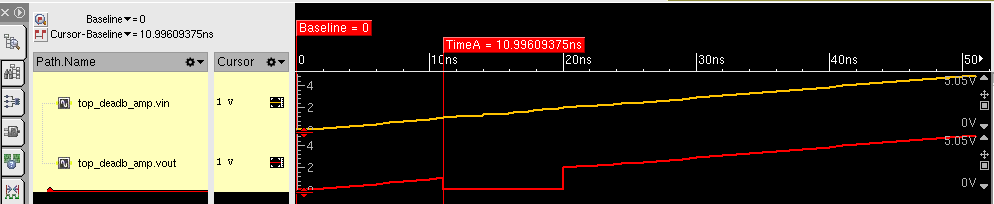
In a  waveforms, here is a result of simulation: 
  • while input is incrementing between 0 and 5V , output is following it except “deadband” in the range of 1-2V when the output is 0V:


© 2011-2019 ASIC Stoic. All rights reserved

Wednesday, September 28, 2011

Verilog AMS: Code examples

Resistor, Capacitor, Inductor, RLC Circuit, Voltage and Current Sources, A Simple Circuit, Relay Digitally controlled Relay, Comparator, Simple 16-bit digital-to-analog converter model, Simple DAC ( digital input async. or no clock involved),DAC ( digital input async. or no clock involved, but  with reference voltage), Simple DAC ( digital input sync. on clock ), Analog tristate buffer, Voltage deadband amplifier, Hysteresis

Code examples

Resistor


In general, a resistor is a relationship between voltage and current, as in
v = ri
where v represents the voltage across the resistor, i represents the current through the
resistor and r is value of resistance of resistor.
v = V(p,n)
i = I(p,n)
v = ri

module resistor (p, n);
inout p, n;
electrical p, n;

parameter real R = 1.0;
analog
V(p,n) <+ R * I(p,n);
endmodule


Capacitor

A capacitor is a relationship between voltage and charge, as in where v represents the voltage across the capacitor, q represents the charge through the capacitor and c is capacitance of capacitor:

q = cv

Capacitors current  is related to its charge like this:
i = dq/dt

So for a linear capacitor, current is:

i = c dv/dt

which is encoded as a Verilog-A/MS contribution statement as
I(p,n) <+ c * ddt(V(p,n));


// Linear capacitor
module capacitor (p, n);
parameter real c=0; // capacitance (F)
inout p, n;
electrical p, n;
analog
I(p,n) <+ c * ddt(V(p,n));
endmodule

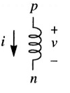
Inductor


An inductor is a relationship between flux and current, where Φ represents the flux across the inductor, i represents the current through the inductor, and l is inductance of inductor.
Φ = li
flux is related to the voltage using:
v = dΦ/dt

the constitutive relation between inductance, voltage and current is:
v = l di /dt


// Linear inductor
module inductor(p, n);
parameter real I=0; // inductance (H)
inout p, n;
electrical p, n;
analog
V(p,n) <+ I * ddt(l(p,n));
endmodule


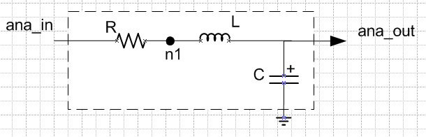
RLC Circuit


module rlc_behav(ana_in, ana_out) ;
inout ana_in, ana_out ;
electrical ana_in, ana_out ;

parameter real R=1, L=1, C=1 ;

electrical n1 ;

analog begin
V(ana_in, n1)    <+ R*I(ana_in, n1)        ;
V(n1, ana_out) <+ L*ddt(I(n1, ana_out)) ;
I(ana_out)        <+ C*ddt(V(ana_out))     ;
end

endmodule


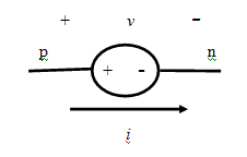
Voltage and Current Sources

Constant voltage source


// DC voltage source
module vsrc (p, n);
parameter real dc=0; // dc voltage (V)
output p, n;
electrical p, n;
analog
V(p,n) <+ dc;
endmodule


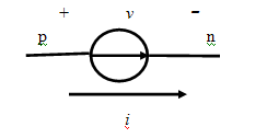
Constant current source

// DC current source
module isrc (p, n);
parameter real dc=0; // dc current (A)
output p, n;
electrical p, n;
analog
l(p,n) <+ dc;
endmodule


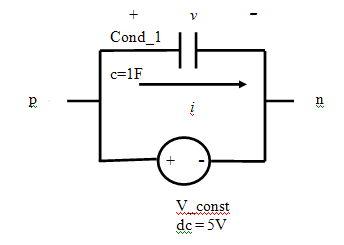
A Simple Circuit


//A simple circuit
`include “V_const.vams”
`include “condensator.vams”
module smpl_ckt;
electrical p,n;

V_const        #(.dc(1)) V_const (p,n);
condensator #(.c(1F)) Cond-1  (p,n);
endmodule

Relay

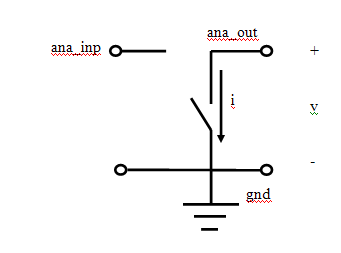
A relay is a switch controlled by analog input (ana_inp),ideal in the sense that when the relay is closed ( ana_inp > treshold ), there is no voltage on its output (ana_out), and when it is open( ana_inp < treshold ) there is no current flowing though its ana_out output contact.


Verilog-A/MS model for an ideal relay.
// Ideal relay
`include “disciplines.vams”
module relay (ana_in, ana_out);
parameter real treshold =0;
output ana_out;
input ana_in;
electrical ana_out, ana_in;

ground gnd ;
analog begin
@(cross( V(ana_in) – treshold , 0 ))
;
if (V(ana_in) > thresh)
V(ana_out) <+ 0;
else
l(ana_out) <+ 0;
end
endmodule

Digitally controlled Relay


module switch (p, n, s);
input s;
output p, n;
logic s;
electrical p, n;
analog begin
if (s)
V(p, n) <+ 0.0;
else
l(p, n) <+ 0.0;
end
endmodule


Comparator

 
The input of this module is an analog input ( ana_inp ) and  the output is a logic signal ( dig_out ).

The output changes when the ana_inp crosses a certain voltage threshold, described as absolute value of parameter offset and parameter hysteresis. The parameter hysteresis provides the capability to add a hysteresis between the lower and the upper thresholds.

// Comparator with logic output
module comparator ( dig_out, ana_inp );
parameter real offset           = 0;
parameter real hysteresis = 0.0 from [0:inf);
inout ana_inp;
output dig_out;
electrical ana_inp;
logic dig_out;
reg dig_out;

ground gnd ;

parameter real thrlo = offset – 0.5*hyst; // Lower threshold voltage (V)
parameter real thrhi = offset + 0.5*hyst; // Upper threshold voltage (V)
always @(above(V(ana_inp) – thrhi))
dig_out = 1;
always @(above(thrlo – V(ana_inp)))
dig_out = 0;
endmodule


Simple 16-bit digital-to-analog converter


analog process is sensitive to the value of in at all times

Simple DAC ( digital input async. or no clock involved)

e.g. module dac (out, in);
parameter fullscale = 1.0;
input [15:0] in;
electrical out;
analog
V(out) <+ in * (fullscale/65536);
endmodule


Simple DAC ( digital input sync. on clock )


analog process is only sensitive to the value of in at the instant of a rising edge on clk


module dac (out, in, clk);
parameter fullscale = 1.0;
input [15:0] in;
input clk;
electrical out;
real smpld;
analog begin
@(posedge clk)
smpld = in * (fullscale/65536);
V(out) <+ smpld;
end
endmodule

Analog tristate buffer

This module evaluates the case statement whenever in changes and will set the local
variable value to 0 if in is 0 and to 1 if in is 1. Otherwise it leaves value unchanged.

Finally, it tests the value of in and if not z it drives V(out) with value, otherwise it
leaves out un-driven.

module buf3 (out, in);
input in;
output out;
electrical out;
real value;
analog begin
@(in)
case (in)
1'b0: value = 0;
1'b1: value = 1;
endcase
          
if (in !== 1'bz)
V(out) <+ value;
end
endmodule

Voltage deadband amplifier

If the input voltage is greater than vin_high or less than vin_low, the amplifier is active.
When the amplifier is active, the output is gain times the differential voltage between the input voltage and the edge of the deadband.

When the input is in the deadband between vin_low and
vin_high, the amplifier is quiescent and the output voltage is zero.


module vdba(in, out);
input in ;
output out ;
electrical in, out ;
parameter real vin_low = -2.0 ;
parameter real vin_high = 2.0 ;
parameter real gain = 1 from (0:inf) ;

analog begin
if (V(in) >= vin_high) begin
V(out) <+ gain*(V(in) - vin_high) ;
end
else if (V(in) <= vin_low) begin
  V(out) <+ gain*(V(in) - vin_low) ;
end
else begin
V(out) <+ 0 ;
     end
 end

endmodule


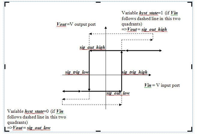
Hysteresis


//--------------------
// hysteresis
//
// -  rectangular hysteresis
//

module hysteresis(Vin, Vout);
input Vin ;
output Vout;
electrical Vin, Vout;
parameter integer hyst_state_init=1;
parameter real Vout_high = 1 ;
parameter real Vout_low = -1;
parameter real Vout_high = 1 ;
parameter real Vout_low = -1;

  integer hyst_state;
  real    Vout_val;

  analog begin

     @ ( initial_step ) begin
      hyst_state = hyst_state_init;
     end

     @ (cross (V(Vin) - Vout_high,1) )
        if (hyst_state == 0)
           hyst_state = 1;

     @ (cross (V(Vin) - Vout_low,-1) )
        if (hyst_state == 1)
           hyst_state = 0;
 
     if (hyst_state == 1) begin
           Vout_val = Vout_high;
     end
     else begin
           Vout_val = Vout_low;
     end

     V(Vout) <+ transition (Vout_val);
  end
endmodule

© 2011 ASIC Stoic. All rights reserved.