Here are some implementation details related to the specification outlined in the other blog entry: ASIC Mix signal Specification: Automotive application: ASIC's Supply Pin connected to a car battery ( reffered as “Specification”).
The implementation will be divided on analog and digital part.
Analog part
To monitor VBAT_uv or VBAT_ov we could use analog comparators. Here is an example of Unbuffered, Two-Stage CMOS Operational Amplifier that we could use an analog comparator.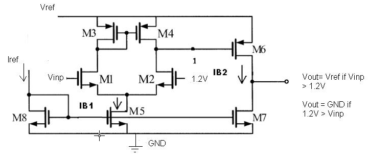
In the Specification it was mentioned just VBat ( car battery voltage ) but to use the comparator we will need in the ASIC couple more reference voltages and currents.
- a reference current Iref for a current mirror used in the comparator
- a reference voltage Vref for alimentation of comparator transistors
- a reference voltage 1.2V (used in voltage comparison). Here is an assumption made that the reference voltage 1.2V is a very stable voltage produced by another analog circuit present in the ASIC: e.g. bandgap.
Here is a hint how to use two instances of the comparator to produce VBAT_uv and VBAT_ov.

There is no need to detect VBAT_ov and VBAT_uv if a digital block of the ASIC Mix signal is under POR ( Power-On-Reset). VBAT_ov and VBAT_uv signals will exit analog block of the ASIC and enter the digital block, but if digital block is under reset, the register flag vbat_ouv is not recorded anyway.
Digital part
Output of the analog part ( or its comparators ), VBAT_uv and VBAT_ov are inputs to digital part. A reasonable assumption here is that digital block is designed in synchronous manner meaning it is using only one clock (“clk”).Before any use of non synchronous digital input signals VBAT_uv and VBAT_ov should be first resynchronized to the clock domain clk using 2 Dff back to back.
t_VBAT_uv and t_VBAT_ov are implemented also in digital block.
© 2011 ASIC Stoic. All rights reserved.
